REMOVING AND INSTALLING TRAINLING ARM Important! Rear wheel alignment must be checked after installation - see Gr. 32. Remove side panel - see Gr. 41. Remove wheel - see Gr. 36. Unscrew brake disc, parking brake cable and ABS signal sender - see Gr. 34. Remove output shaft - see "Removing Wheel Bearings" in 33 41.  32 00 000 41 35 000 41 35 000 41 35 000 32 00 000 41 35 000 41 35 000 41 35 000
| |
Unscrew nut and pull off lower control arm. Installation: Use washer (1). Replace nut. Tightening torque = 100 Nm. | 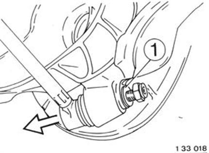 |
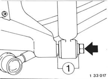
Unscrew bolt. Installation: Use washers (1). Tightening torque = 77 Nm with car in normal position (see Specifications for Gr. 32). See Specifications
|  |
Unscrew bolts. Installation: Tightening torque = 42 Nm. | 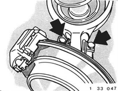 |
Unscrew and remove bolt (1). Take off adjusting sleeve (2). Installation: Tightening torque = 77 Nm. | |
Rubber Mount Assembly: 1 Trailling arm 2 Rubber mount 3 Rubber cap 4 Threaded sleeve E Direction of pressing-in A 59.5 mm | 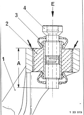 |