CHECKING AND ADJUSTING FRONT AND REAR WHEEL ALIGNMENTL Check and adjust wheel alignment only with a recommended electronic wheel alignment tester (see Workshop Equipment Planning). See page 32 - 0 for testing conditions and specifications. 1 Toe 2 Camber 3 Caster (with 10° or 20° wheel lock) 4 Toe difference angle (with 20° wheel lock) 5 Wheel displacement 6 Camber 7 Rear wheel position 8 Toe 9 Geometrical axis | 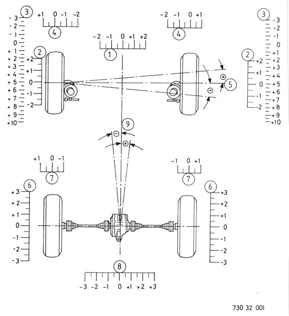 |
Front Axle Adjust in Toe and Toe Difference Angle: Turn steering gear to straight ahead position (marks on case and steering shaft). | |
Loosen bolts of tie rods. Adjust toe of left and right wheels to the specified value (see page 32 - 0) by turning the tie rods. Installation: Make sure that ball joints and dust covers are not twisted. Tightening torque = 14 Nm. | 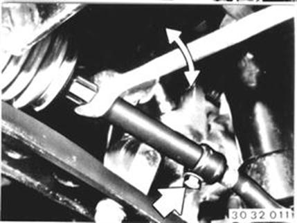 |
Rear Axle Wheels must be on turntables to make adjustments. | |
 |
|
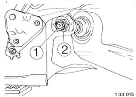
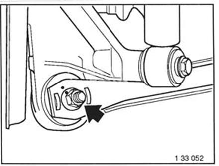
Adjusting Camber (Aluminum Control Arm): Loosen nut. Adjust camber to the specified value (see page 32 - 0) by turning the eccentric bolt. Installation: Tightening torque = 77 Nm. | 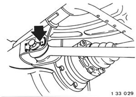 |
Adjusting Camber (Steel Control Arm): Loosen nut. Adjust camber to the specified value (see page 32 -0) by turning the eccentric. Installation: Tightening torque = 110 Nm with car loaded down to normal position (refer to Specifications).  See Specifications See Specifications
|  |
Correcting Camber: Eccentric mounts can be installed to correct camber deviation caused by the summation of unfavorable tolerances by ± 30´. Important! These measures must never be used to eliminate deviations in wheel alignment caused in an accident. Example: Specified camber: - 22`... - 1° 22´ Actual camber: - 1° 30´ + correction: + 30´ New actual camber: - 1° | |
Eccentric mounts are marked on the bores with + and -. Press knurled head bolts in the "+" or "-" marked bores as required (see example) with Special Tool 31 3 130. | 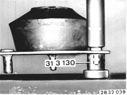 |
Important! Knurled head bolts must be perpendicular in the mounts and bear flush. | 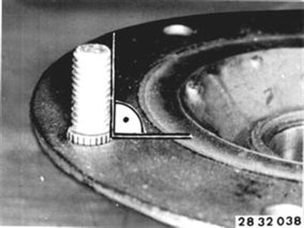 |