REMOVING AND DISASSEMBLING STEERING COLUMN ASSEMBLY Remove trim panel for dashboard st bottom - see Gr 51. Remove seat - see Gr. 52. Pull off horn button. Mark position of steering wheel to steering spindle. Unscrew and remove nut with washer. Important! The steering wheel can only be pulled off after unlocking the steering lock. Installation: Replace self-locking nut. Tightening torque = 76 Nm.  51 43 000 52 10 000 51 43 000 52 10 000
|  |
Installation: Check position of collar (1) to snap ring (2). | 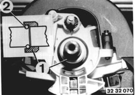 |
Unscrew steering column casing. | 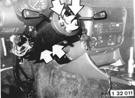 |
Remove clamping bolt. Press steering spindle down. Installation: Clamping bolt is located in locking groove of the steering spindle. Replacing self-locking nut. Tightening torque = 19 Nm. | 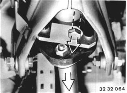 |
Note: Mark position of splines with dots of paint. Screw on adjusting nut far enough that displacement force is 40 ± 25 N. | 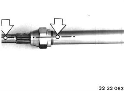 |
Unscrew bolts (1). Chisel off screw (2). Installation: Replace self-locking nuts. Tightening torque = 22 Nm. Tighten new shear-off screw (2) until it shears off. | 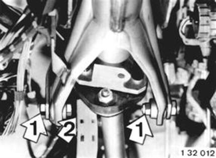 |
Installation: Use spacer. | 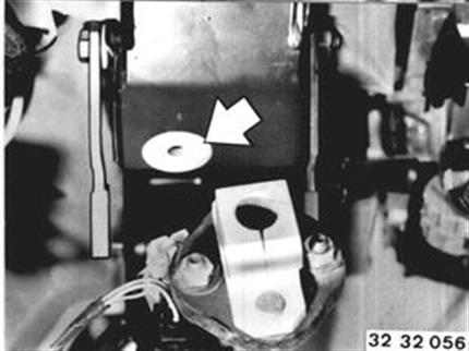 |
Disconnect plugs on steering column. Unscrew bolts and remove steering column. | 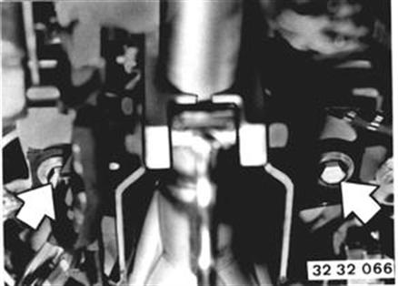 |
Installation: Use spacer. Tightening torque = 22 Nm (16 ft. lbs.). | 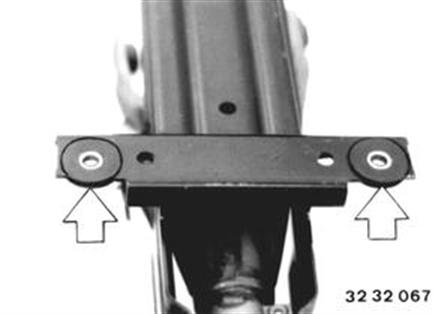 |
Disassembling Steering Column: Pull off plug. Compress retaining hooks and pull off switch. | 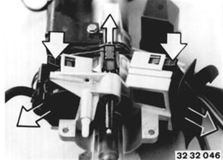 |
Press down on retaining hooks with a screwdriver and take off ignition switch. Unscrew electric lead holder and relay socket. | 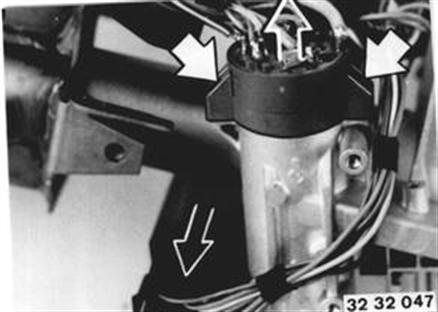 |
Compress and pull out horn contact. Installation: Lubricate lightly with grease in area of the spring. | 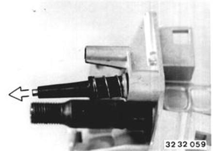 |
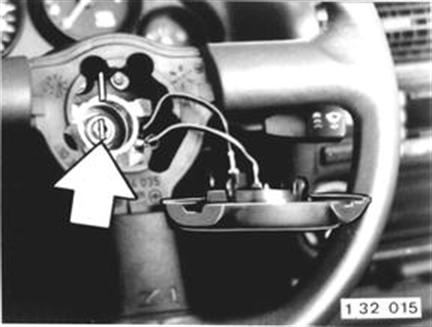
Turn ignition key to position "R", press a 1.2 mm (0.047") diameter wire into the bore and pull out the lock cylinder. | 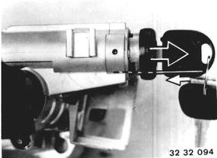 |
Lift out snap ring (1). Take off washer (2), spring (3) and support (4). Installation: Stem of support (4) faces the bearing. | 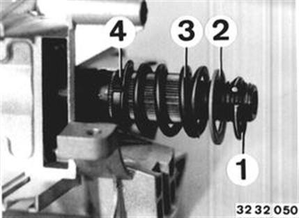 |
Installation: Place snap ring (1) on Special Tool 32 3 052 and mount with Special Tool 32 3 051 (hammer knock). Counterhold on steering spindle. | 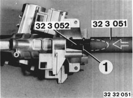 |
Chisel off the shear-off screw. Pull off steering lock. Knock out bearing, if necessary. | 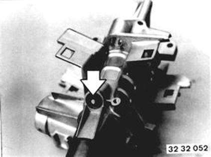 |
Installation: Slide steering lock on outer tube. Tighten Torx screw until it shears off. | 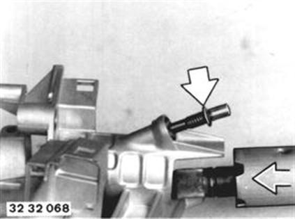 |
Lower Steering Spindle Bearing: Lift out snap ring (1) and take off collar (2) with support (3). Knock out bearing, if necessary. Installation: Stem of support (3) faces the bearing. Install snap ring with Special Tools 32 3 051 / 052. | 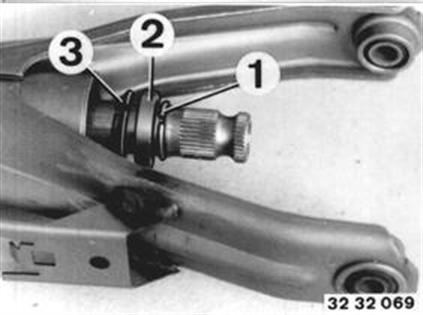 |
Unbend lockplates (5). Unscrew screws (1 ... 3). Screw (1) = left-hand threads Installing Procedures (Order): 1. Screw in M 8 x 22 left-hand thread screw (1) with lockplate (5). Torque = 14 Nm. Check distance A = 1.75 + 1.25 mm between lever and clamp. 2. Screw in M 8 x 28 screw (2) with lockplate (5) and nut (4). Torque = 9 Nm. 3. Tighten nut (4). Torque = 14 Nm. 4. Tighten hexagon nut (3) with lever (6) in "CLOSED" position. Torque = 16 Nm. 5. Lock lockplate (5) by bending. | 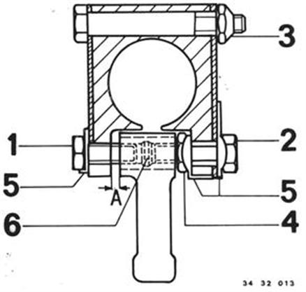 |