Remove bolt. Push up steering spindle. Installation: Bolt must be located in groove of the steering shaft. Replace self-locking nut. Tightening torque = 19 Nm. | 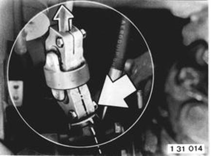 |
Installation: Turn steering wheel and front wheels to straight ahead position (marks on case and steering shaft aligned). Mount steering spindle on the steering gear in such a manner that the clamping slot of the universal joint is aligned with mark on the steering gear. | 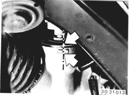 |
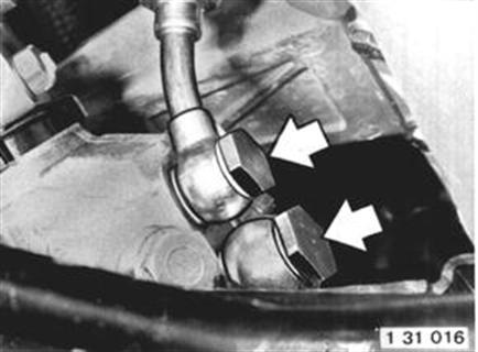
Draw hydraulic fluid out of tank. Disconnect hoses. Insert dust caps in open connections. Installation: Replace seals. Tightening torque: M 14 = 35 Nm M 16 = 40 Nm Bleed power steering - see Gr. 32.  32 13 000 32 13 000
|  |
Unscrew holders on left and right sides. Installation: S = Washer Tightening torque = 42 Nm for 8.8 bolts 47 Nm for 9.8 bolts | 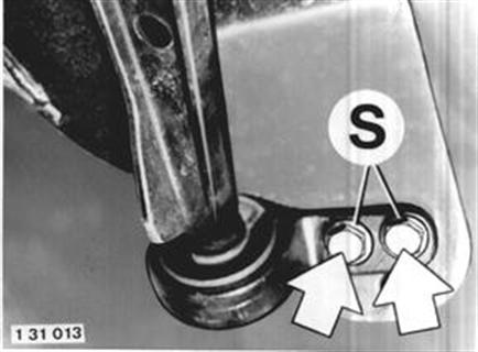 |
Unscrew engine mounts on left and right sides. Installation: Turning lock of mount must engage in the axle carrier. | 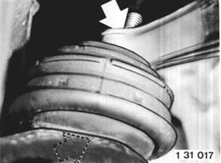 |
Suspend engine on Special Tool 00 0 200. Support front axle carrier from underneath with a garage jack. | 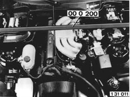 |
Unscrew bolts on left and right sides. Installation: S = washer Tightening torque = 42 Nm for 8.8 bolts 47 Nm for 9.8 bolts | 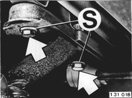 |
Unscrew nuts on left and right sides. Lower front axle slowly. Important! Spring struts must not be allowed to tilt outward or sag - this could damage the ball joints. Installaiton: Replace self-locking nuts. Tightening torque = 22 Nm. | 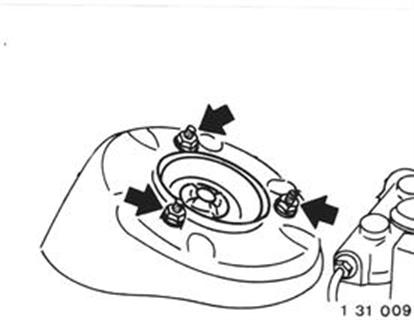 |