REMOVING AND INSTALLING ENGINE Disconnect battery ground lead. Remove transmission - see Gr. 23.  23 00 000 23 00 000
| |
 |
|
Drain coolant on engine block. |  |
Removing Power Steering Pump: Loosen nut (1) and loosen the drive belt by turning toothed element (2). | 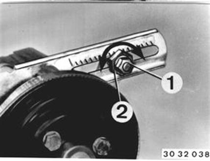 |
Unscrew ground strap. Unscrew bolts and take off power pump. Hoses remain connected. Installation: Tighten the drive belt before tightening the bolts. | 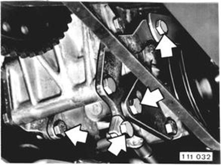 |
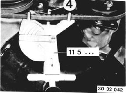
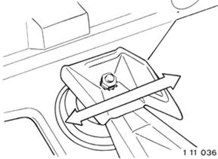
Installation: Tighten drive belt. Torque the toothed element to 8 ... 8.5 Nm (5.8 ... 6.1 ft. lbs.) and lock by tightening the nut. Check the drive belt tighteness with Special Tool 11 5 020, correcting if necessary. Hook (4) must bear on tip of tooth. Bleed power steering - see 32 13. 32 13 000
|  |
Removing Air Cleaner: Pull off plug (1). Loosen clamp (2). | 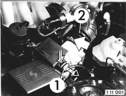 |
Unscrew nuts on rubber elements from the outside of the wheel house. Take off the air cleaner. Note: Nuts are accessible through openings in the wheel house trim panel. | 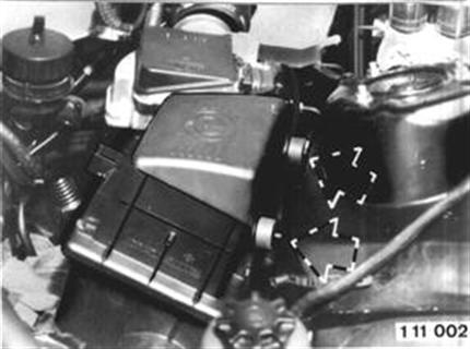 |
Loosen lamp for leads on the air flow sensor. | 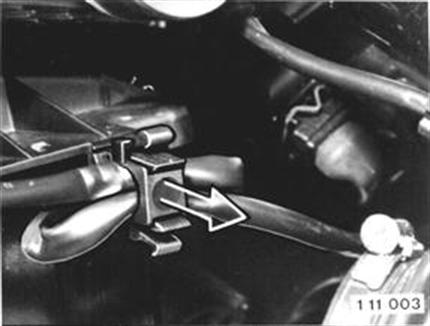 |
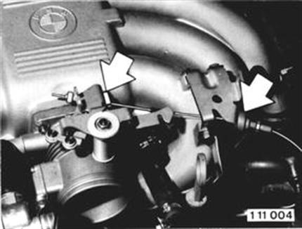
Disconnecting Throttle Cable: Unscrew throttle cable on the throttle valve and holder. Installation: Adjust throttle cable - see Gr. 35. 35 41 000
|  |
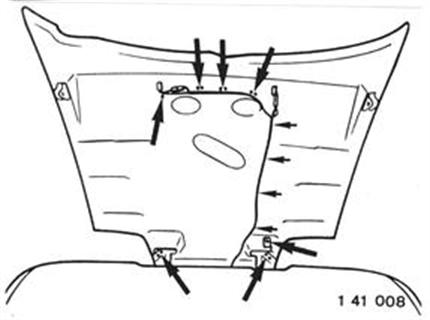
Removing Fan Cowl: Lift out expander rivets on left and right sides. Pull out the fan cowl upwards. | 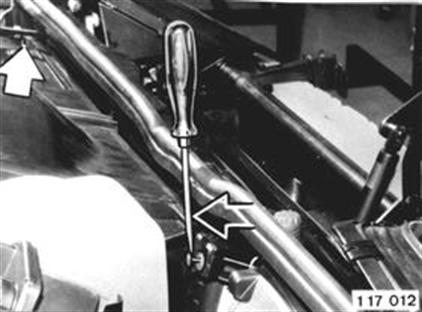 |
Installation: Attach retainers at left and right as well as bottom center. | 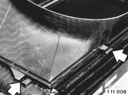 |
Disconnecting Water Hoses and Tank: Disconnect coolant hose on the thermostat housing and radiator. | 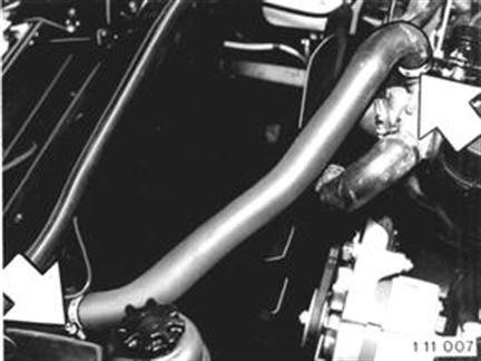 |
Disconnect coolant hose on bottom of radiator. | 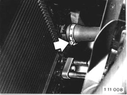 |
Disconnect coolant hose on the expansion tank. | 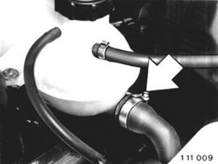 |
Unscrew expansion tank and heat shield. | 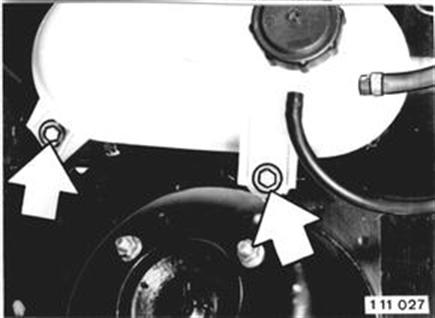 |
Disconnect heater hoses on the heat exchanger or engine. | 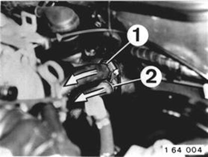 |
Disconnecting Oil Cooler Hoses: Unscrew bolt. Pull hoses off of the oil cooler. Installation: Check seals, replacing if necessary. | 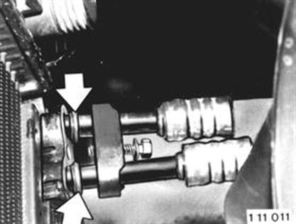 |
Installation: Check location of feed and return hoses. 1 = From oil cooler 2 = To oil cooler | 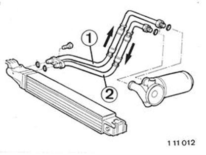 |
Disconnecting Fuel Hoses: Disconnect fuel hoses on the injection pipe and fuel pressure regulator. | 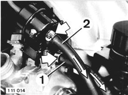 |
Installation: Hose (1) = Feed to Injection pipe Hose (2) = Return from fuel pressure regulator |  |
Unclip hoses in holder on the engine block. | 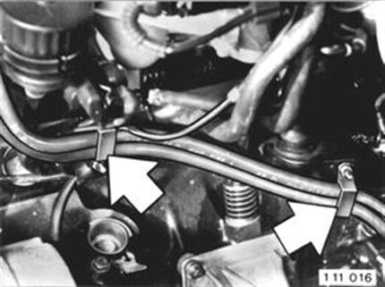 |
Pull hose off of the carbon canister. | 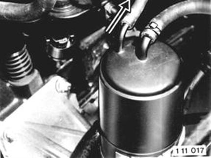 |
Disconnect vacuum hose for the brake booster on the manifold. | 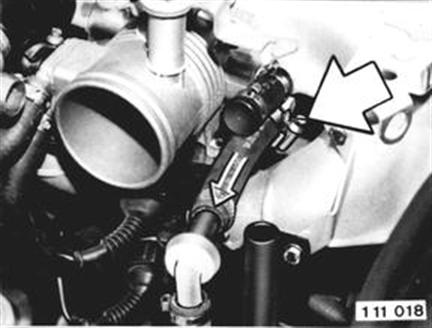 |
Disconnect Engine Electrically: Pull off ignition leads. Lift off cap. Unscrew leads (1 and 15). Unclip ignition leads and wires in holders. | 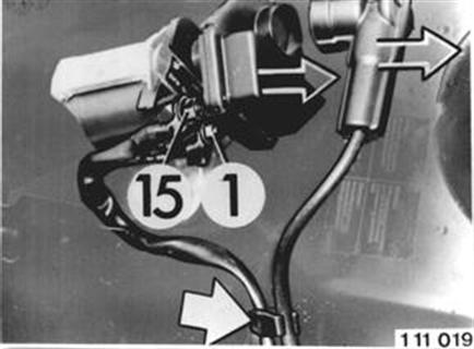 |
Unclip plug in holder on the engine compartment wall. Disconnect plug (bayonet connection). | 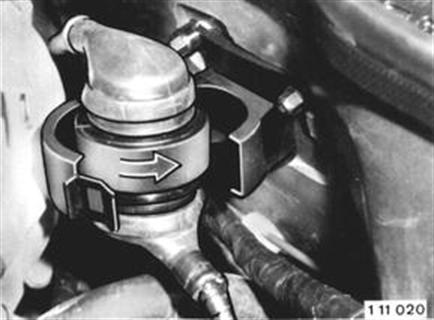 |
Unscrew electric lead cover. Unclip holder with oxygen sensor plug. | 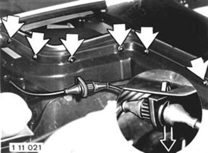 |
Unscrew electric lead at ground point on the wheel house. | 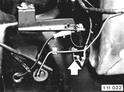 |
Unscrew electric lead at positive (+) connection point on the engine compartment wall. | 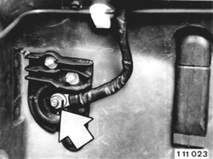 |
Unscrew cover on the electric box. | 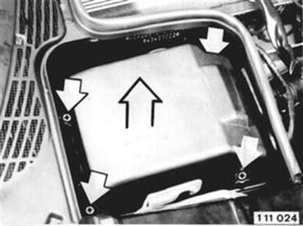 |
Unscrew bracket for the rubber grommets. Installation: Insert retaining pin in the provided hole. | 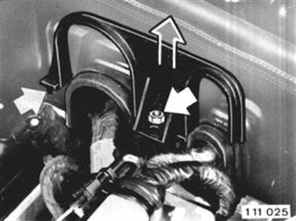 |
Pull out relays with sockets. Disconnect plug. Pull off plug on control unit. Unscrew electric lead on the connection point. | 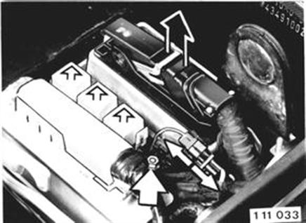 |
Location of Relays: 1 DME master relay 2 Electric fuel pump relay 3 Oxygen sensor control relay | 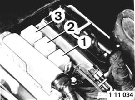 |
Pinch off wire holders. Pull wire harness complete with plugs and relays out of the electric box. | 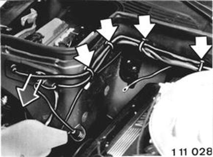 |
Lifting Out Engine: Unscrew left and right engine mounts on the frame arms. | 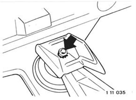 |
Installation: Check routing of hose the power steering. | 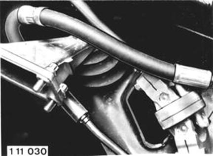 |
Installation: Slots are provided in the frame arms. Tighten engine mounts without tesnion. If applicable, take up missing clearance with help of the slot in the final drive take-up (see Group 33). 33 00 000
|  |
Attach Special Tool 11 0 020 on the front and rear ends of the engine. Lift out engine. | 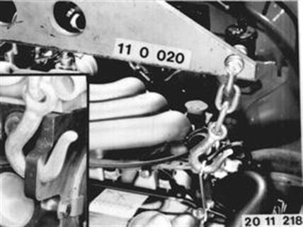 |