| |
REPAIRING INSERTS WITH
STRIPPED THREADS AND
FORCED OUT OR DAMAGED
INSERTS
- Floor Must Not Be Damaged -
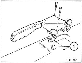
Example: Parking Brake Inserts
Remove attachments.
1 - Parking brake insert
|  |
| |
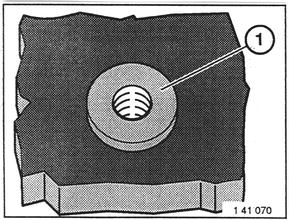
Removing Insert with Stripped Threads:
Screw in left-hand tap, drill hole in insert if
necessary and unscrew insert with left-hand
tap.
Caution!
Maximum depth for drilling and screwing
in of left-hand tap is 15 mm.
Make sure top layer to floor is not damaged
while unscrewing the damaged insert.
|  |
| |
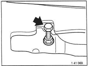
Removing Forced Out or Overtightened
Insert - Threads Not Damaged:
Screw screw with nut in insert.
Screw nut tight on insert.
Remove screw with insert by turning
counterclockwise.
|  |
| |
Roughen floor in area aroud the repair
zone with grain size P 80 sandpaper.
Clean area around repair zone with
acetone.
Caution!
Work with gloves.
| |
| |
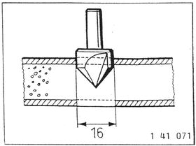
Countersink bore for insert approx. 4 to 5 mm
deep with a 16 mm dia. countersink
until tip laminate has been drilled through.
Caution!
Extract drilling abrasion.
|  |
| |
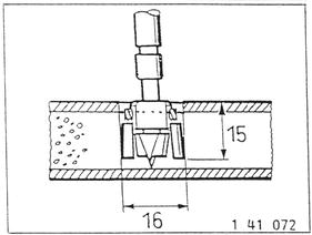
Open up bore with a 16 mm dia. forstner
bit or wood borer.
Use a drill with depth stop.
Depth: 15 mm!
Caution!
Extract drilling abrasion.
|  |
| |
Check threads of new insert for easy
screwing, correcting if necessary.
Screw a screw in insert until it is flush
with bottom edge of the insert.
Install insert and check whether collar of
insert bears on floor all around and connector
can be installed without stress;
correct bore if necessary.
Clean insert with acetone.
Caution!
Work with gloves.
| |
| |
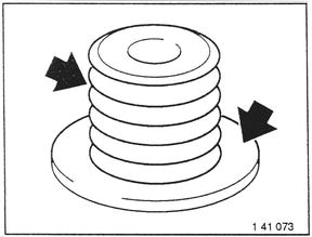
Mix cement to instructions.
Note:
Allow the cement to thicken for overhead
work by waiting a short time after mixing.
Note:
Apply mixed cement after 45 minutes at
the latest.
|  |
| |
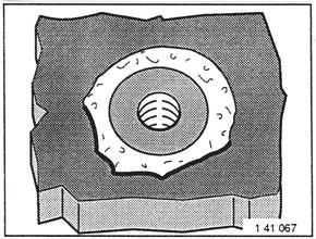
Fill 1/3 of bore with cement.
Coat edge of bore as well as collar and
outside surface of insert with cement.
|  |
| |
Install insert with screwed-in screw in
prepared bore.
Only Parking Brake Inserts:
Unscrew screw, press insert firmly.
Note:
Cement should runout along edge of
insert and produce a collar around the
insert.
|  |
| |
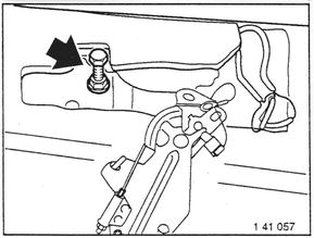
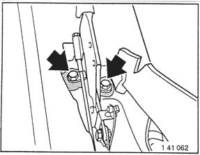
Only Parking Brake Inserts:
Mount parking brake lever immediately after
cementing.
Important!
Tighten bolts only finger tight.
|  |
| |
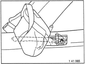
Only Parking Brake Inserts:
Hold parking brake lever in position, e.g.
by applying a bag of sand.
Check seating of insert after 3 minutes,
pressing on again if necessary.
Recheck seating of insert after 1 hour.
|  |
| |
Other Inserts:
Unscrew screw two turns to let trapped air
escape.
Press insert firmly, if necessary hold in
position (e.g. with adhesive tape).
Note:
Cement should run out along edge of
insert and produce a collar around the
insert.
| |
| |
Other Inserts:
Check seating of insert after 3 minutes,
pressing on again if necessary.
Unscrew screw.
Recheck seating of insert after 1 hour.
| |
| |
All Inserts:
Wait 24 hours before subjecting cement to
loads.
Ambient temperature should not be below
20° C.
Do not use other source of heat (e.g. heat
radiators) to speed up the hardening
process.
Touch up damaged paint finish.
Tighten screw of insert - refer to torque
specifications!
Reinstall attachments.
| |
| |
INFORMATION FOR Z 1 BODY REPAIRS
General Information:
Z 1 body (steel sheet metall) is subjected to the following restrictions in
ragards to partial replacement of sheet metal parts.
Partial replacement of the engine carrier between front axle take-up points
is not approved. Check for sufficient accessibility for out cutting points. If
the right-hand side engine carrier is partially replaced after the front axle
take-up point, a standard production installed reinforcement plate inside
of the engine carrier could be cut though (depending on location of cut).
Tis reinforcement plate is no longer required for partial replacement and
can be omitted.
Other body parts can be replaced separately insofar as welding spots are
accessible.
Reinforcement plates must always be used for partial replacements (engine
carrier or body part). Procedures for partial replacement repairs (engine
carrier or body part) are the same as those for partial replacement of
the engine carrier in front of the front axle for other BMW models.
| |
| |
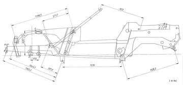
Z 1 FRAME CONTROL DIMENSIONS
- Sheet 1 -
Dimensions in mm; tolerance ± 2.0 mm.
Note:
Use the following value for a rough
check only.
Professional repairs are only possible
with use of approved attachments and
straightening bench.
A Upper front cross member mounting bore
B Lower front cross member mounting bore
C 8 mm dia. bore in support member end plate
D Front take-up on inside of engine carrier
E Rear take-up on inside of engine carrier
F 8 mm dia. inside higher bore of spring mount
G Front side panel take-up/slot
H Front car jack take-up point
J Lower take-up pin for door guide rail (A-pillar)
K Upper take-up pin for door guide rail (A-pillar)
L 8 mm dia. outside bore of sun visor holder
M Rear car jack take-up point
N Seat belt/reel take-up point
O Top storage box lid hinge/upper bolt take-up point
P Bolt head in rear bumper holding plate
R 8 mm dia. bore in upper embossment of rear side panel
|  |
| |
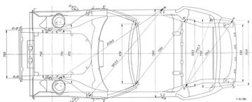
Z 1 FRAME CONTROL DIMENSIONS
- Sheet 2 -
Dimensions in mm; tolerance ± 2.0 mm.
Note:
Use the following values for a rough
check only.
Professional repairs are only possible
with use of approved attachments and
straightening bench.
A Upper front cross member mounting bore
B Lower front cross member mounting bore
C 8 mm dia. bore in support member end plate
D Front take-up on inside of engine carrier
E Rear take-up on inside of engine carrier
F 8 mm dia. inside higher bore of spring mount
G Front side panel take-up/slot
H Front car jack take-up point
J Lower take-up pin for door guide rail (A-pillar)
K Upper take-up pin for door guide rail (A-pillar)
L 8 mm dia. outside bore of sun visor holder
M Rear car jack take-up point
N Seat belt/rael take-up point
O Top storage box lid hinge/upper bolt take-up point
P Bolt head in rear bumper holding plate
R 8 mm dia. bore in upper embossment of rear side panel
|  |