REPAIRING COMPOSITE FIBER MATERIAL COMPONENTS (FLOOR PLATE AND HOOD/LIDS)ON Z 1 Repairs can only be carried out correctly with approved repairing materials Basic equipment repair it (available from Cartool) Material repair kit (available form BMW Parts) and strict conformance with the discribed procedures. Repairs are described in details in the SIP film "Repairing Composite Fiber Material Components (Floor Plate and Hood/Lids) on Z1". Stripped threads of threaded inserts in the car´s floor plate can be repaired by installing helicoil inserts - refer to SI 41 03 90 (178). When repairing the floor and hood/lids (glass fiber/epoxid sandwich) a difference must be made between a) scratches and breaks in top surface (repaired to paintwork instructions in Repair Manual) and b) scrateches and breaks extending deep in material (repaired to following instructions). Refer to safety precautions on page 41-00/2. Uncover damaged spot enough until undamaged layers are accessible. Clean damaged spot generously with rags soaked in acetone; wipe dry afterwards. Determine actual size of damage. Knock on surface around damaged spot 20 cm away with a hard item (e.g. screwdriver) to find invisible separation of top layer laminate from the foam core. Insufficient adhesion can be noticed by the difference in sound. Important! If hood/lids are damaged, knock around the damaged spot on the inside and outside! Mark actual size of damage. Check whether reapring is possible (refer to concerned repair zone). Grind off top layer laminate (1) with a angle grinder fitted with a soft sanding disc, grain size 60 to 80, in such a manner that the foam core (3) plus an additional 10 mm around the damaged spot is visible. Taper edges with an eccentric grinder, grain size 80 to 100. Taper length "L" is removed from ground glass fiber material (2). Floor: 2 layers, L = 30 to 40 mm 4 layers, L = 40 to 50 mm Hood/Lids: L = 35 to 45 mm Transfer size of damaged spot to polyester sheet (50 x 50 cm) with a water proof pencil to scale of 1 : 1; add 1 cm all around. | |
REPAIRING HOLES, CRACKS, CHAFINGS AND DELAMINATIONS OF ONE DAMAGED TOP LAYER Refer to safety precautions on page 41-00/2! Foam core will have to be replaced, if there are holes or chafings deeper that 3 mm. - Only for replacement of foam core, cut out foam core around the damaged spot in rectangular shape with a carpet knife and remove foam core with a mortise chisel. - Extract or blow off abrasion from damaged spot. - Only for replacement of foam core, cut new piece of foam from repair kit to size and fit in (gap size not larger than 3 mm). - Clean taper with clean, acetone-soaked rags; wipe dry afterwards. - Don´t clean the foam surface; danger of absorption! -Air dry at least 15 minutes. - Cut all glass fiber tissue layers to size of damaged spot. - Orientate tissue as in the original component; refer to picture of concerned repair zone for number of layers. - Cut perforated sheet to size of damaged spot plus about 2 cm. - Cut absorption fleece to size. - Prepare vacuum sheet. -Paste on vacuum sealing tape; watch out for size of heating blanket. Don´t pull off the protective sheet! - Place perforated sheet on polyester sheet. -Mix epoxy resin and epoxy thick sheet. - Place first layer of glass fiber tissue on perforated sheet and soak with epoxy resin until white spots are no longer visible. - Position other layers of glass fiber tissue and soak each layer thoroughly with epoxy resin; don´t use too much resin. - Only for replacement of foam core, install foam core with thick resign. -Brush in damaged spot with thick resin; eliminate small irregularties and holes in foam core with thick resin. - Lift repair laminate with perforated sheet off of polyester sheet, place on repair surface and press on firmly. Important! Perforated sheet must be on outside. - Install absorption fleece, heating blanket and absorption fleece to the vacuum assembly on page 41-00/10. - Pull protective sheet off of vacuum sealing tape; press on and seal vacuum sheet. - Switch on vacuum pump; produce seal by pressing vacuum sheet on vacuum sealing tape. - Hardening Repaired Surface: Normal hardening 12 hours are room temperature (more than 20° C) possibly overnight or fast hardening 3 hours at 60° C with help of heating blanket. Always temper 1 hour at 120° C with help of heating blanket. - Remove vacuum assenbly. -Shape repaired surface by sanding by hand or with a vibration sander. Only grind off protruding repair laminate; fill in repaired surface. - Paint repaired surface on floor with black paint*. - Paint repaired surface on hood/lids to BMW specifications.  * Source if Supply: BMW Parts * Source if Supply: BMW Parts
| |
REPAIRING HOLES; CHECKS, CHAFINGS AND DELAMINATIONS OF TWO DAMAGED TOP LAYERS Refer to safety precautions on page 41-00/2! Important! First build up one top layer as already described. Do not yet replace the foam core! Vacuuming is not possible as the second top layer is also damaged. - Replace foam core. - Build up second top layer in same manner as first top layer. Now vacuuming is possible. | |
REPAIRING BROKEN EDGES ON HOOD/LIDS Refer to safety precautions! - Cut out foam core around the damaged spot in rectangular shape with a carpet knife and remove foam core with a mortise chisel. - Extract or blow off abrasion from damaged spot. - Cut new piece of foam from repair kit to size and fit in (gap size not larger than 3 mm). - Clean taper with clean, acetone-soaked rags; wipe dry afterwards. - Don´t clean the foam surface; danger of absorption! - Air dry at leat 15 minutes. - Cut all glass fiber tissue layers to size. - Orientate tissue as in the original component; refer to picture od concerned repair zone for number of layers. - Cut three additional layers of glass fiber tissue for the edge zone in widths of 3, 4 and 5 cm. - Produce shape of edge with wax plate (repair kit). - Place perforated sheet on polyester sheet. - Mix epoxy resin and epoxy thick resin. - Place first layer of glass fiber tissue on perforated sheet and soak with epoxy resin until white spots are no longer visible. - Position other layers of glass fiber tissue and soak each layer thoroughly with epoxy resin; don´t use too much resin. - Install foam core with thick resin. - Brush in damaged spot with thick resin; eliminate small irregularties and holes in foam core with thick resin. - Lift repair laminate with perforated sheet off of ployester sheet, place on repair surface and press on firmly. Important! Perforated sheet must be on outside. - Vacuuming is not possible. - Hardening Repaired Surface: Normal hardening 12 hours are room temperature (more than 20° C) possibly overnight or fast hardening 3 hours at 60° C with help of heating blanket. Always temper 1 hour at 120° C with help of heating blanket. - Sand, fill in and paint repaired surface. | |
REPAIR ZONES - FLOOR BOTTOM Zone 1: No repairing permitted. - Seat rail zone (overlaminated area + 5cm safety distance) - Stabilizer mounts with 5 cm safety distance around bores - U-profile floor cementing zone + 3 cm safety distance Repair this type of damage to instructions described on pages 41-00/3 and 41-00/4. Refer to safety precautions on page 41-00/2! Zone 2: Repairing with 3 layers of glasse fiber issue permitted; taper length: 30 to 40 mm. - Flat floor area Zone 3: Repairing with 5 layers of glass fiber tissue permitted; taper length: 40 to 50 mm. - Tunnel zone - Battery mounting zone 10 cm around inserts - Accelerator pedal stop 10 cm around insert - Zone around inserts for side member panels up to max. 3 cm in front of sheet metal U-profile Permissible damage size in Zones 2 and 3: Cracks - max. 30 cm long Holes - max. size 15 x 15 cm Chafings - max. 30 x 15 cm Tissue orientation: Tissues running in forward direction. Important! Tissues must be installed without stress. | 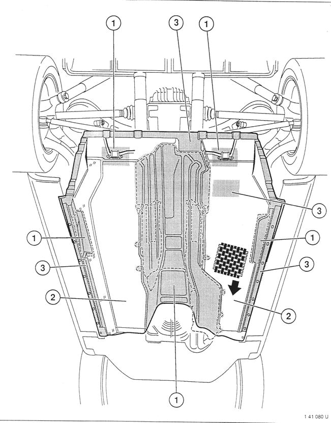 |
REPAIR ZONES - FLOOR TOP Zone 1: No repairing permitted. - Seat rail zone (overlaminated area + 5 cm safety distance) - Stabilizer mounts with 5 cm safety distance around bores - U-profile floor cementing zone + 3 cm safety distance Repair this type of damage to instructions described on pages 41-00/3 and 41-00/4. Refer to safety precautions on page 41-00/2! Zone 2: Repairing with 3 layers of glass fiber tissue permitted; taper length: 30 to 40 mm. - Flat floor area Zone 3: Repairing with 5 layers of glass fiber tissue permitted; taper length: 40 to 50 mm. - Tunnel zone - Battery mounting zone 10 cm around inserts - Accelerator pedal stop 10 cm around insert - Zone around inserts for side member panels up to max. 3 cm in front of sheet metal U-profile Permissible damage size in Zones 2 and 3: Cracks - max. 30 cm long Holes - max. size 15 x 15 cm Chafings - max. 30 cm long, max. 5 cm wide, max. 10 cm damaged foam core Delaminations - max. size 30 x 15 cm Tissue orientation: Tissues running in forward direction. @@L Important! Tissues must be installed without stress. | 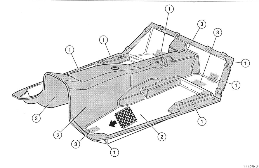 |
REPAIR ZONES - ENGINE HOOD Zone 1: No repairing permitted. - 12 cm zone around mounting points for retaining hooks - Hump zone with 5 cm safety distance from hump cement - Z-profile Repair this type of damage to instructions described on pages 41-00/3 and 41-00/4. Refer to safety precautions on page 41-00/2! Zone 4: Repairing with 4 layers of glass fiber tissue permitted; taper length: 35 to 45 mm - Top of lid - Bottom of lid, excluding zone 1 Permissible damage size in Zone 4: Cracks - max. 15 cm long Holes - max. size 10 x 10 cm Chafings - max. 15 cm long, max. 5 cm wide, max. 10 cm damaged foam core Broken corners - max. size 5 x 5 cm Broken edges - max. size 3 x 15 cm Delaminations - max. size 30 x 15 cm Tissue orientation: Tissues running in forward direction. Important! Tissues must be installed without stress. | 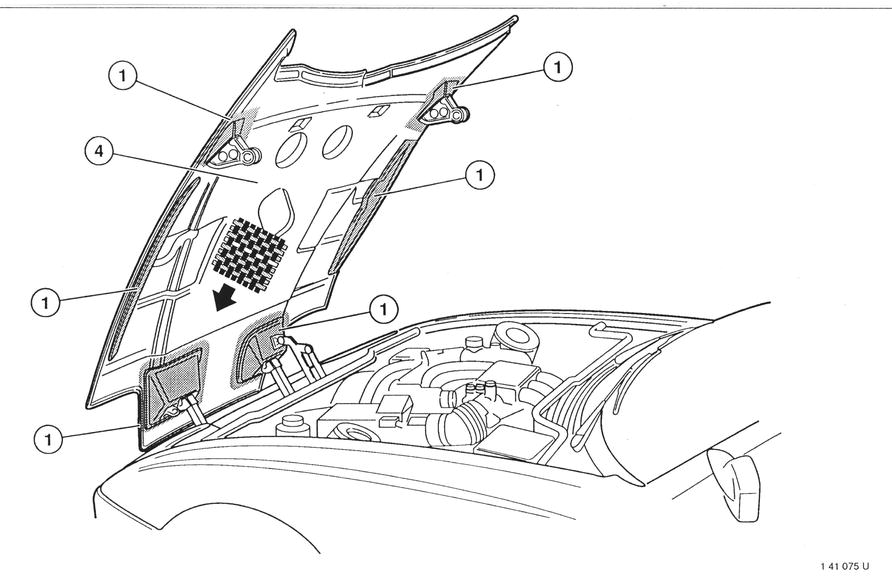 |
REPAIR ZONES - TOP STORAGE BOX LID Zone 1: No repairing permitted. - 12 cm zone around mounting points for lid brackets - 12 cm zone around mounting points for lid retainers Repair this type of damage to instructions described on pages 41-00/3 and 41-00/4. Refer to safety precautions on page 41-00/2! Zone 4: Repairing with 4 layers of glass fiber tissue permitted; taper length: 35 to 45 mm - Top of lid - Bottom of lid, excluding zone 1 Permissible damage size in Zone 4: Cracks - max. 15 cm long Holes - max. size 10 x 10 cm Chafings - max. 15 cm long, max. 5 cm wide, max. 10 cm damaged foam core Broken corners - max. size 5 x 5 cm Broken edges - max. size 3 x 15 cm Delaminations - max. size 30 x 15 cm Tissue orientation: Tissues running in forward direction. Important! Tissues must be installed without stress. | 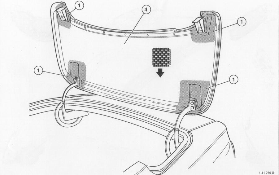 |
REPAIR ZONES - TRUNK LID Zone 1: No repairing permitted. - 12 cm zone around mounting points for lid brackets - 12 cm zone around mounting points for lid retainers Repair this type of damage to instructions described on pages 41-00/3 and 41-00/4. Refer to safety precautions on page 41-00/2! Zone 4: Repairing with 4 layers of glass fiber tissue permitted; taper length: 35 to 45 mm - Top of lid - Bottom of lid, excluding zone 1 Permissible damage size in Zone 4: Cracks - max. 15 cm long Holes - max. size 10 x 10 cm Chafings - max. 15 cm long, max. 5 cm wide, max. 10 cm damaged foam core Broken corners - max. size 5 x 5 cm Broken edges - max. size 3 x 15 cm Delaminations - max. size 30 x 15 cm Tissue orientation: Tissues running in forward direction. Important! Tissues must be installed without stress. | 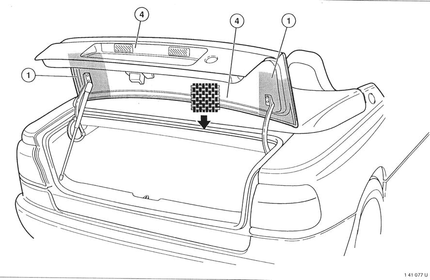 |
VACUUM ASSEMBLY FOR REPAIRING COMPOSITE FIBER MATERIAL COMPONENTS 1 Vacuum connection 2 Electric connection 3 Sealing tape 4 Absorption sheet 5 Absorption fleece 6 Heating blanket 7 Absorption fleece 8 Perforated sheet 9 Repair laminate 10 Thick resin 11 Top layer laminate 12 Foam core | 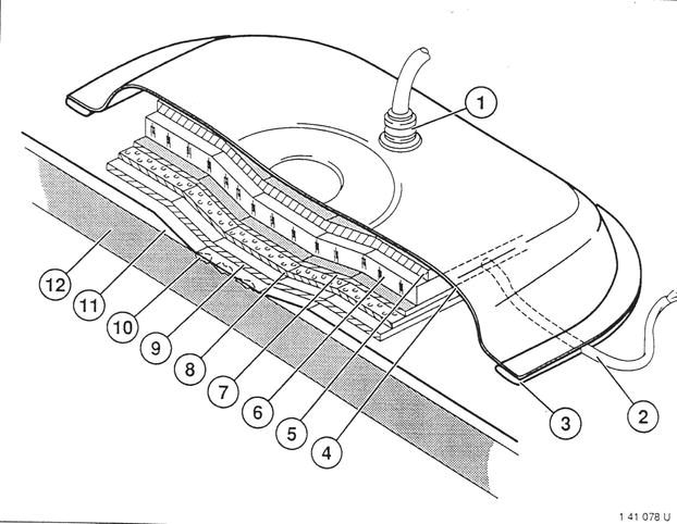 |